
Challenges are such a cool way to compel people to learn. The inherent part of any challenge that really drives the outcomes is the fact that there is a deadline. Between our tendencies to procrastinate, oversimplify, under-budget, continuously refine and otherwise "let perfect be the enemy of done", it is absolutely true that nothing happens without a deadline. This is true with software and is magnified with robotics.
That's why every robot you've ever seen could be better - some creative person was rushed to meet a deadline by a more practical person.
This story begins with some people I ran into at RoboGames and the Makerfaire, introducing...
The Home Brew Robotics Club
I recently started attending this local club for a few meetings now and found that this was a fun and diverse group. It has been enriching to see what other people are working on.
A few meetings each year are designated as 'challenges' and everyone is compelled to demo something. I wanted to give this a shot so I figured I would start at the beginning.
The Tabletop Challenge, Phase I
The "first" challenge - the one I think is intended to be the most approachable, is explained as:
"Phase I: Go from one end of the table to the other and back."
My curiosity was piqued. I immediately jumped the gun and started to think of the various ways to solve it. Reading through the next "phases" of the challenge ( and the following, more complicated challenges ) caused me to slow down and think bigger. The next phase requires new capabilities.
The best part about this is that everyone is welcome and you can demo anything. Especially for "phase I" it doesn't need to be, and is not by definition, done. Mine is a rats nest and I actually tried to make it look nice 😆
Design Philosophy / Creative Restriction
I didn't want to do this with a solution that had already been used, or at least not without adding my own twist. I also wanted to experiment and learn some new skills ( which I think is the point of any of this ).
A few months back I had been dabbling with putting machine learning models onto embedded devices, mostly because I was surprised that this was possible at all. It amazed me that I could use my own laptop to train an image classifier, export a model, and then use it to make inferences when running on a microcontroller. ( See MobileNet and MicroMobileNet )
So I decided my angle would be to train some computer vision models for a tiny consumer device and see how far that will get me.
I love using the cheap, widely available components since they tend to be very well crowd-documented. I wasn't trying to overkill this challenge ( becomes ironic ), so sticking with cheap stuff seemed to be the way to go.
Paradoxically powerful, cheap and tiny. Something like that.
Project Development Philosophy
Inspired by my recent experiences learning Gazebo alongside the ROS framework, I was also interested in the ways that using simulation could be used in development. I started thinking about all the ways I could validate my idea before starting the build. This became another goal: to start developing the software and simulation before building anything.
But wait 🤔. How does one train a custom image classifier for a robot with specific dimensions, camera angle, optical characteristics ... without building it first?
Normally, as I explained this to my kid, I would take the (built) robot and move it around the table while capturing tons of images of its perspective on the tabletop. Thousands and thousands of images, from all possible angles, and with varying background content ( because other than the tabletop there will be something else in the frame ). These images would then need to be annotated with relevant categories like "left edge", "corner", etc, and be used to train the image classifier. If you are a human like me then you probably see the friction with this approach.
So 🤔 harder
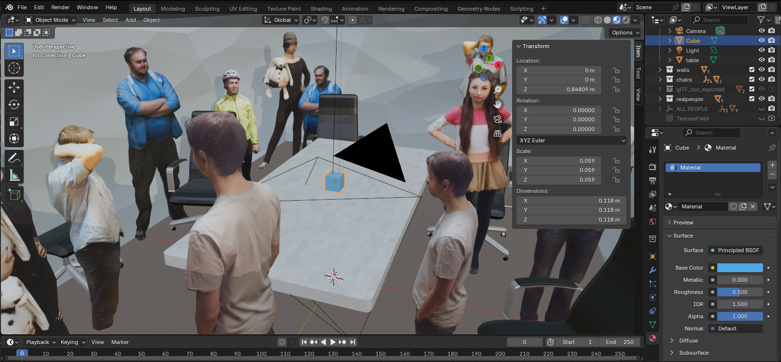
I'm going to simulate my training data! And I know just the tool for it! Another throwback to something I was fiddling with a decade ago: the Blender Python interface!
Retrospect: This was a little tricky to setup. I was using Docker to run Blender "headless" in a container and when I needed to install more python dependencies it needed to be done with Blender's self-contained version of python. It was one of those times that trying to do it with Docker may not have been a win 🤷
Docker Image: lscr.io/linuxserver/blender:latest
I'm going to make a computer do all the painstaking image composition, exposure randomization, background randomization, annotation, and capture. This will result in a much bigger pool of training images that can be programatically filtered and organized into various categories based on position and orientation data I save as (EXIF) metadata.
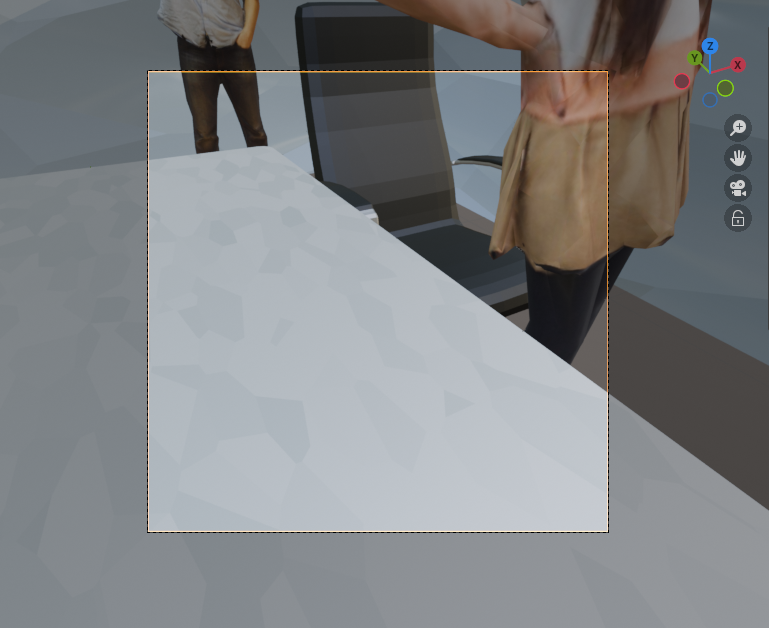
I generated thousands and thousands of images.
$ exiftool training/sets/left/render_20250306-233212.png
File Name                       : render_20250306-233212.png
...
MIME Type                       : image/png
...
Warning                         : Invalid EXIF text encoding for UserComment
User Comment                    : {"camera_position": {"x": -0.3533795475959778, "y": -0.8208436965942383, "z": 1.100000023841858}, "camera_rotation": {"x": 1.0, "y": -0.0, "z": 0.4193033277988434}}
Image Size                      : 128x128
Megapixels                      : 0.016
even though it complained about it, I put JSON in 'User Comment' and got away with it
The metadata about the camera position combined with the known, static positioning of the table is enough to make assumptions about what (edges mostly) the camera sees from where.
Modeling the Problem
The way that I ultimately modeled this problem is to treat the robot's domain as the 180 degrees in front of it. It doesn't know anything about it's heading, it only cares about what is in front of it, and it doesn't back up. It's very zen.
It looks forward and moves forward if there is room. If it detects an oblique edge it steers away from it. If it conclusively finds a blunt edge or a corner it turns completely around.
Having this simple outline helped me focus on what models to develop.
Modeling Categories / Training
I can do simple classifiers given the amount of available RAM for storing and running the model ( in addition to all the other things going on ), meaning probably 5 categories maximum. For my domain that's no problem. I never imagined that I would be able to train one model that would provide all the possible feedback to solve this challenge. Instead I set out to design multiple models ( each with just a few categories, sometimes binary ) that provide different bits of useful information about the robot's position.
Once I decided on an idea for a model I would use some scripts to separate the pool of available training data into the datasets that I wanted. For example, for one model I named "cornerNet", I created two sets of images for "corner" and "not corner". I could easily separate them by filtering on the metadata that included their X, Y position and Z rotation. Similarly I could build sets of images for "left edge of table", "right edge of table", "blunt edge of table", etc.
Again, these are not all combined into one model. Each model only sees things as one of two or three mutually-exclusive categories.
I also grayscaled and normalized the exposure of my training images in order to match the same preprocessing that will be done with the image captured from the camera.
The actual model training was done on my laptop with a regular old CPU, which took about ten minutes per model. At the end of training these fun little report cards tell you whether your model learned anything, and how it performed on each category.
              precision    recall  f1-score   support

           0       0.93      0.93      0.93       746
           1       0.94      0.93      0.94       503
           2       0.87      0.91      0.89       513
           3       0.91      0.88      0.89       534

    accuracy                           0.91      2296
   macro avg       0.91      0.91      0.91      2296
weighted avg       0.91      0.91      0.91      2296
Training report for one of my models. F1 of 91% is OK but not great.
The really nice thing about MicroMobileNet is that it outputs an embedded C++ file that contains the model and all the code required to run an inference with it. It's like a standalone computer vision model!
Validating in Simulation
In retrospect this may have been kind of pointless - because it only validates that it 'works' in the same simulated environment where it trained. I used the hardware (via an API) to run the inferences, which I suppose proved early-on that they would all fit and run in a reasonable amount of time. Otherwise

This helped reveal the 'corner' problem, where I was failing to consider a corner as the end of the table and trying to correct my way out of it with endless left and right corrections.
Using Blender lacks the physics simulation that Gazebo would provide, but this task is much more about what the camera sees. It would have been more educational to run these simulations in different virtual rooms, different tables, backgrounds.
Models V1
Here is how far I got before I got bored with training and decided that the measured and simulated performance of each was "good enough":
- EdgeNet: Is this nowhere near an edge, approaching an edge, or clearly the left of right edge of the table?
- LeftNeitherRightNet: Is this facing the left edge of the table, the right edge of the table, or neither?
- HeadingNet: (poorly named) Is this very near & facing the left edge, kinda near and facing the left edge, kinda near and facing right edge, or very near and facing right edge?
- CornerNet: Is this a closeup view of the corner of a table, or not?
- DangerNet: "Are you in danger of falling off the table, or not?" This one sounds cool but almost completely failed to generalize to real imagery.
Hopefully inferences from those models on any given image will give enough information to continue safely.
Hardware Development & Bench Testing
Lots of stuff needed to happen on the hardware side:
- connecting to Wifi (eventually hosting our own AP)
- setting up the basic web server for the API and telemetry
- configuring the camera and the image (pre)processing pipeline
- loading the trained models
- which included MicroMobileNet for making predictions from images
- setting up the stepper motors
- navigation and command logic to ( roughly ) replicate real world distances and angles
It was just one thing at a time. Copilot was really instrumental here and allowed me to focus on the broader strokes and less about the C++ syntax, which is not ... one of the first 4-5 languages I've learned. I also cobbled from other simpler projects I've done that were stepping stones to this point.
Physical Build
Putting this off until the end is a new experience for me, but I even drafted it in 3D to embrace the plan-it-first philosophy.
I knew the camera height was going to make for an awkward and potentially unstable shape, but all the heavy components riding at the bottom should help.
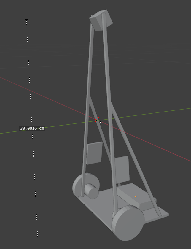
😆
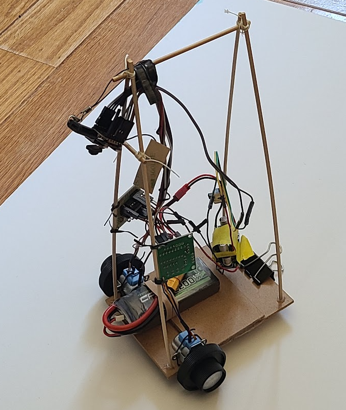
Retrospect: The camera height may not have been that important after all, considering the simple features these models are recognizing (edges, corners)
Then the Real-Life Challenges
Don't worry about that interference on the power lines causing your MCU to reset, ChatGPT will just render you a helpful "wiring diagram" to show you how a few capacitors can clean things up 🤣
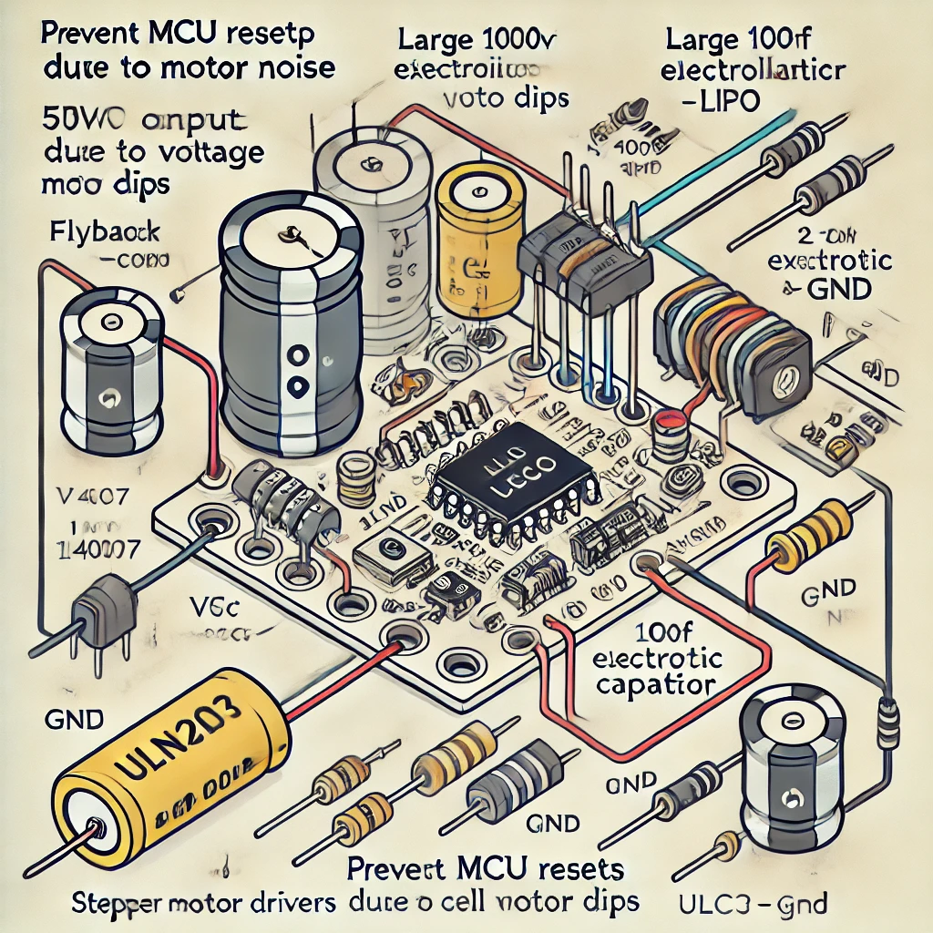
There were a few issues to tackle with transitioning completely to onboard power:
- I selected a 2S Lipo as the battery which runs through a variable buck converter which I adjusted to about 5.7V because I also needed a ...
- diode to prevent the 5V pin on the MCU from trying to become the power source for the whole system when it gets plugged in with a USB cable. I want to still be able to plug this in on the bench ( and switch the motors on with battery power at the same time ). This ensures the 5V pin is a one-way street for powering the MCU. The forward voltage drop is compensated-for by the slightly higher voltage setting on the buck converter.
- The capacitors though? I tried to add these to my circuit but they didn't stop the MCU resets, so I ultimately went with 2 separate power supplies for the MCU and motor driving.
Once that was sorted out I had some time to play with how the code interprets all the inferences. The short story is that it comes down to vote among the models ( I think this is similar to what is called a Mixture of Experts ). Some will vote for steering to the right, others for steering to the left, continuing straight, or stopping and reversing course. The votes are weighed and a few other time-series metrics are checked ( e.g. "have we seen blunt edge three time in a row?" ), to decide how to proceed with motor commands.
Test & Iterate
For a low-stakes test environment I would just put a white poster-board down on the floor and see if it would avoid the edges.
Eventually I got to the point where it was pretty reliable but slow. It wasn't that compelling to watch it as it iterated through capturing an image, making inferences, and giving a short drive command. Near the 11th hour I decided to refactor a few things to make it run more continuously and it was worthwhile. It still pauses for some breaks while driving, but most of those are to let the motors cool off.
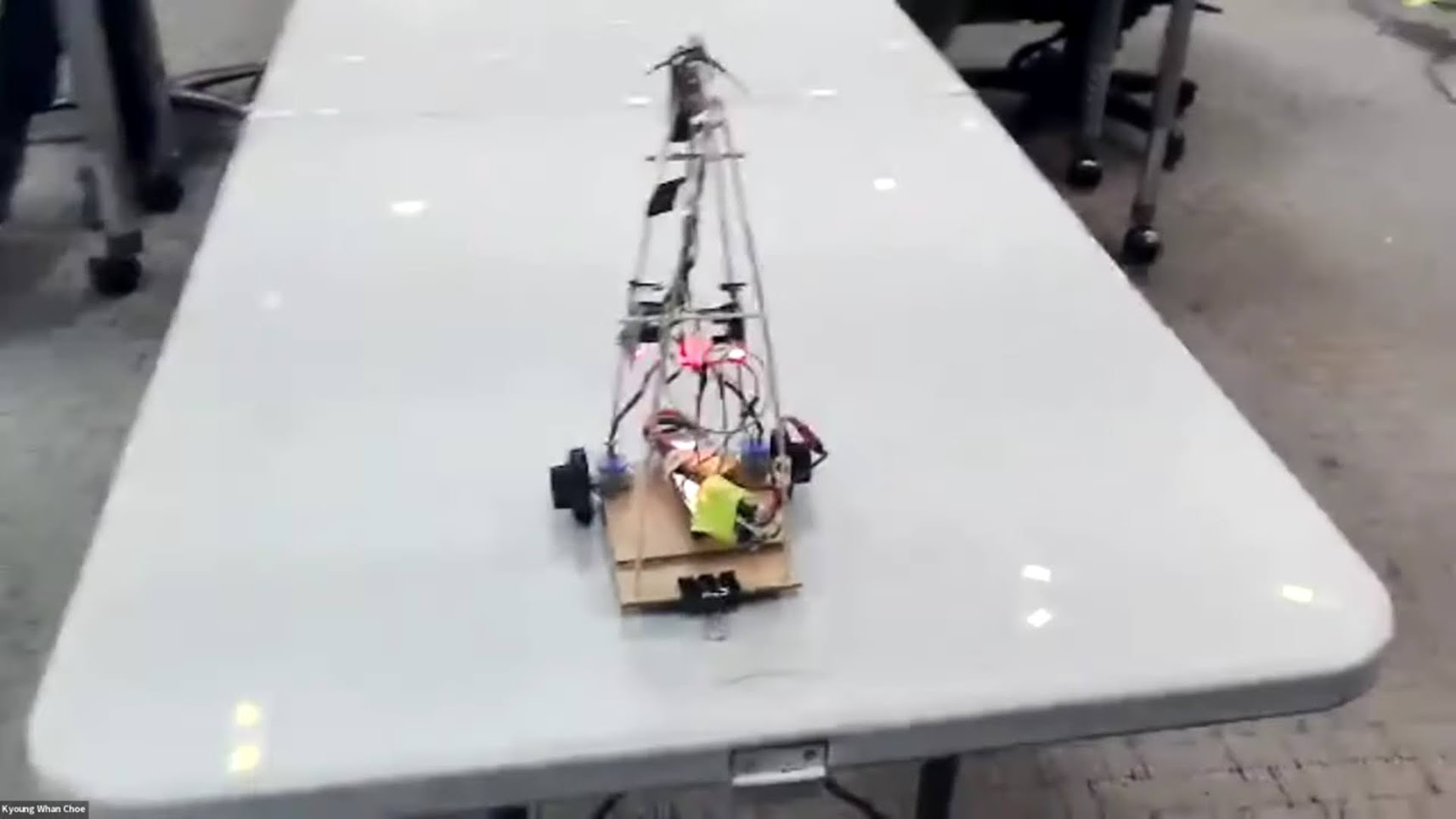
Showtime
It worked! I avoided the edge of the table several times. Luckily this table was pretty much exactly what I expected. I was pleased to have kept it to 1 battery and 1 power switch.
Final BOM
- Xiao ESP32 S3 Sense Microcontroller
- Motor driver boards with ULN2003 x2
- Mini stepper motors x2
- 2S (8V) battery
- Variable DC-DC buck converter x2
Conclusion
I was very pleased. I stuck to my original creative restrictions and learned a lot as a result.
Stepper motors were a good choice but these cheap ones just heat up and aren't compatible with many of the smaller driver boards.
Update: I've already started R&D for Phase II and things are getting crunchy trying to stick with the ESP32. I am learning a lot about tensorflow as I'm trying to train an object detector and keep the model small.
